Bode plots drawing hand
Table of Contents
Table of Contents
If you’ve ever found yourself scratching your head over how to draw bode plot, you’re not alone. Despite its importance in electrical engineering, many students find this concept confusing and difficult to grasp. In this article, we’ll break down the steps needed to draw a bode plot, from start to finish.
When it comes to understanding bode plots, many students struggle with identifying the appropriate transfer function to work with. It can be difficult to know where to start when presented with a complex circuit diagram or a convoluted expression for the transfer function. Additionally, students often struggle with figuring out where to plot the various elements (magnitude or phase) on the graph itself.
The good news is that drawing a bode plot is actually a step-by-step process that can be broken down into manageable parts. The first step is to identify the transfer function and then separate it into its constituent elements (poles, zeros, and constant values). From there, we can apply certain rules to each of these elements to determine how they contribute to the final shape of the bode plot.
In summary, the key steps to drawing a bode plot are to identify the transfer function, separate it into its constituent elements, and then apply the appropriate rules to each element to determine its effect on the magnitude and phase of the graph. Throughout this process, it’s important to keep in mind the key keywords and concepts associated with bode plots, including logarithmic scales, decibels, and frequency response.
How to Draw Bode Plot: An Example
When I first started learning about how to draw bode plots, I was completely overwhelmed. I couldn’t figure out where to start, and the various rules and equations for each element seemed like a jumble of random information. However, once I got the hang of breaking down the transfer function and applying the rules systematically, it became much easier for me to understand how to draw a bode plot.
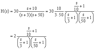
Let’s walk through an example to illustrate this process. Say we’re given the transfer function T(s) = (s+1)/(s^2+2s+2). The first step is to rewrite this in terms of separate elements, which in this case are the two poles and the zero: T(s) = 1/(s+1) * (1/(s+1) - 1/(s+1+j))
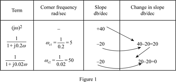
 From there, we can apply the rules for each element. For example, we know that poles contribute -20db/decade to the magnitude plot, and that each pole will shift the phase by -90 degrees. Once we apply these rules to each element, we can add up the individual contributions to get the final bode plot.
The Importance of Bode Plots in Electrical Engineering
Understanding how to draw bode plots is an essential skill for any electrical engineer. Bode plots can be used to analyze complex circuits and determine their frequency response, which in turn can help engineers design circuits that meet specific performance criteria. By visualizing the magnitude and phase response of a circuit, engineers can gain insight into its behavior over a wide range of frequencies and make informed decisions about how to optimize its performance.
Bode Plot Rules and Equations
When it comes to drawing bode plots, there are several key rules and equations that you’ll need to know. For example, you’ll need to understand how to convert between logarithmic and linear scales, how to calculate decibels, and how to use certain formulas to determine the contribution of each element to the final plot. Familiarize yourself with these equations and rules, and practice applying them to different examples to get a feel for how they work in practice.
Complex Poles and Zeros
One of the trickiest aspects of drawing bode plots is dealing with complex poles and zeros. In general, complex poles and zeros will give rise to peaks in the magnitude plot and phase shifts that depend on the damping ratio. To account for these elements, you’ll need to use a combination of trigonometric identities and logarithmic rules to calculate their contribution to the final plot.
Exploring Bode Plots Further
Once you feel comfortable with the basic process of drawing bode plots, there are many ways to explore this topic further. You might try experimenting with different types of circuits or transfer functions, or digging deeper into the mathematical principles that underlie bode plot analysis.
Question and Answer
Q: What is a bode plot?
A: A bode plot is a graphical representation of the frequency response of a system.
Q: Why are bode plots important?
A: Bode plots are important in electrical engineering because they can be used to analyze, design, and optimize complex circuits.
Q: How do you draw a bode plot?
A: To draw a bode plot, you need to identify the transfer function for the system, separate it into its constituent elements (poles, zeros, and constant values), and then apply the appropriate rules to each element to determine its effect on the magnitude and phase of the graph.
Q: What are the key keywords associated with bode plots?
A: Key keywords associated with bode plots include logarithmic scales, decibels, and frequency response.
Conclusion of How to Draw Bode Plot
Drawing a bode plot can seem intimidating at first, but by breaking the process down into its constituent parts, it becomes much more manageable. Whether you’re an electrical engineering student or a professional engineer, mastering the art of drawing bode plots is an important step on the road to becoming a skilled and knowledgeable practitioner in your field.
Gallery
Bode Plot Example | Bode Diagram Example MATLAB | Electrical Academia

Photo Credit by: bing.com / bode matlab magnitude
Rules For Constructing Bode Diagrams - Erik Cheever

Photo Credit by: bing.com / bode example diagrams rules constructing lpsa swarthmore edu
Bode Plot Examples With Solutions | How Do You Make A Bode Plot

Photo Credit by: bing.com / bode magnitude plots nyquist
Mechanics Of Drawing BODE Plots By Hand - An Example - YouTube

Photo Credit by: bing.com / bode plots drawing hand
Bode Plot EXAMPLE - YouTube

Photo Credit by: bing.com / bode plot example


